TM 11-6625-486-14&P
ground clip to the meter chassis and touch the ac probe
d. Tracing Modulator Signal. When performing the
tip to TP501. The vtvm should indicate 4.8 volts.
signal tracing check below, refer to the test setup in
(3) To trace the 900-hertz ac signal where it
circuit board and TP604 on the power supply circuit
modulates the vfo B- voltage, touch the ac probe tip to
board; then proceed as follows:
TP604 (power supply). The vtvm should indicate 2.54
volts.
(1) Turn the vtvm FUNCTION to AC and the
RANGE switch to 10V. Turn the frequency meter
FUNCTION SW to MOD and the RANGE SW to any
range.
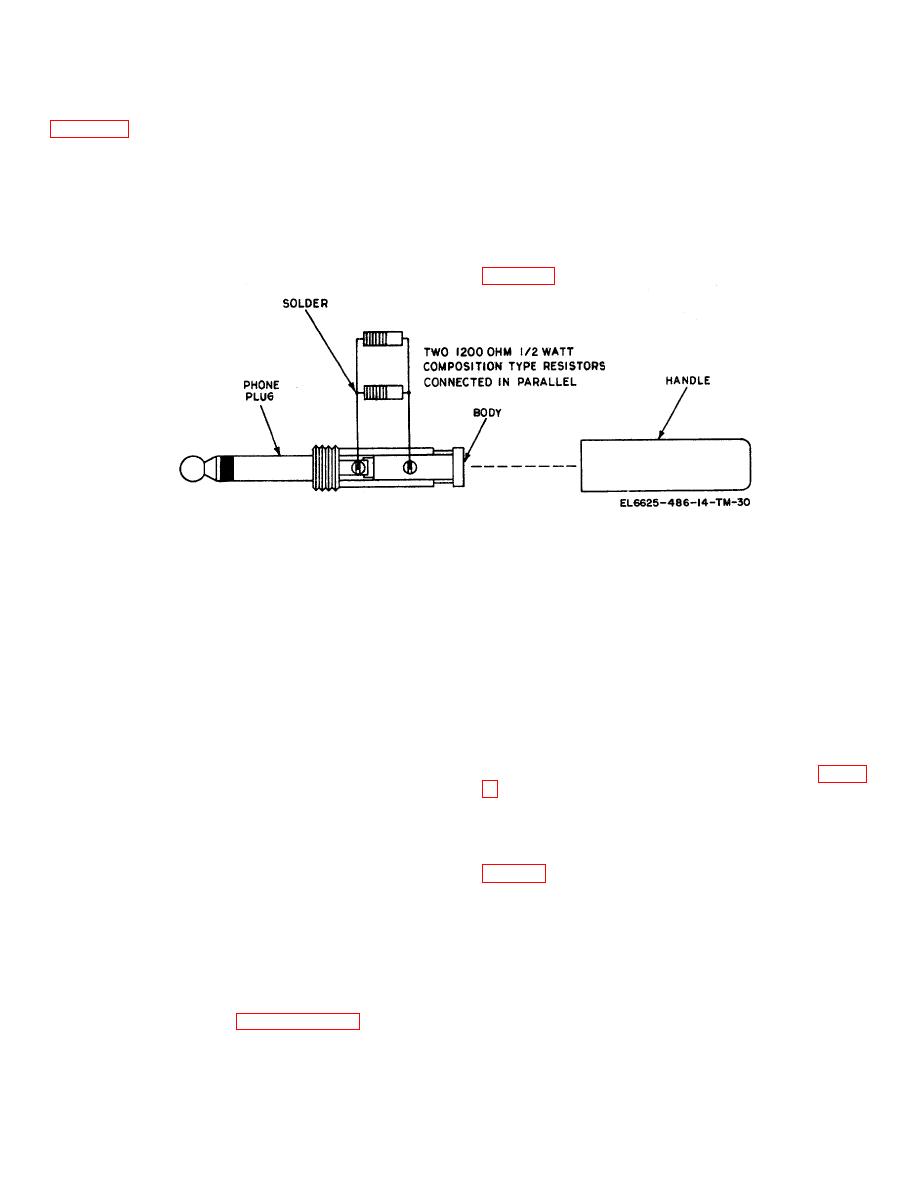
Some of the tests require a 600-ohm dummy load. The
materials required to construct the dummy load are
(2) To measure the modulator 900-hertz ac
listed below. Construct the dummy load as shown in
output signal of oscillator Q501, connect the vtvm probe
dummy load into a PHONES jack and proceed as
a. The following materials are required to fabricate
follows:
the dummy load:
NOTE
(1) Resistor, 1/2 watt, 1,200 ohms (2 each).
Do not plug in the headset.
(2) Phone plug.
a. Using Internal Modulator. For these tests, use
(3) Screw, 2-56 x 1/4 (2 each).
the vtvm ac probe. Turn the vtvm FUNCTION to AC
and the RANGE to 3V.
b. Remove the handle from the phone plug.
(1) Turn the frequency meter FUNCTION SW
c. Connect the two 1,200-ohm resistors in parallel
to MOD and the RANGE SW to A. Rotate the AUDIO
and solder the leads; then connect the two leads to the
GAIN control fully clockwise.
phone plug terminals.
(2) First measure the modulated vfo signal at
d. When a 600-ohm dummy load is specified for
the collector of mixer Q301. This point can be reached
any of the following tests, insert the dummy load phone
through the right side-panel output of the meter (fig. 6-
plug into one of the frequency meter PHONES jacks. If
any difficulty is experienced in connecting test
the probe tip to the collector of Q301. The vtvm should
equipment to this phone plug, use a spare plug and
indicate 2.7 volts.
insert the plug into the other frequency meter PHONES
jack; then connect the test equipment to this plug.
(3) The next step is to trace the signal at the
NOTE
output of the first audio amplifier stage. Refer to figures
If a 600-ohm resistor is available, use
FO-2 (1) and 6-5 or 6-6 to locate transistor Q401. Touch
it as a dummy load instead of the two
the ac probe tip to the collector of Q401. The vtvm
1,200 ohm resistors.
should indicate 1.5 volts.
6-11. Signal Tracing of Internally Generated Signals
(4) Locate transistors Q402 and Q403. The
Through Audio Amplifier
vtvm should indicate 0.8 volt at the collector of Q402
and 1.6 volt at the collector of Q403.
Signal tracing of generated signals through the audio
amplifier may be accomplished by use of either the
(5) From the above tests, it should be evident
internal modulator or the crystal oscillator, provided the
that if a signal does not exist at any particular signal
vfo signal is present. Use the 600 ohm dummy load
tracing point, the trouble may be assumed to be in that
constructed according to paragraph 6-12. Plug the
stage.


 Previous Page
