TM 11-6625-486-14&P
GENERAL SUPPORT MAINTENANCE INSTRUCTIONS
Section I. GENERAL
measurements, and off for resistance or continuity
checks.
a. The frequency meter is transistorized. Observe
all precautions given to prevent transistor damage. Make
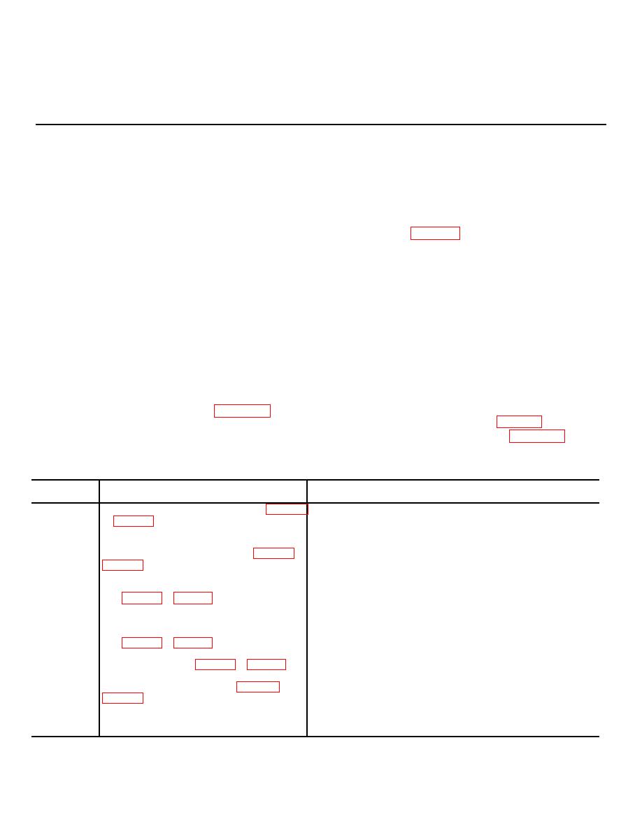
6-2. Equipment Test Points
voltage and resistance measurements in the equipment
only as specified. When measuring voltages, use tape or
The location and purpose of all circuit board test points
sleeving to insulate all but the extreme tip of the test prod.
are outlined in table 6-1. The exact location and the
voltages are given in the references in the Physical
CAUTION
location column.
A momentary short circuit can ruin the
transistor; for example, if the bias is shorted
6-3. Dc Resistances of Transformers and Coils
out, excessive current between the emitter and
a. Before making resistance measurements of the
the base would ruin the transistor. When
windings, determine that the faulty operation is because
resistance measurements are made on the
of a defective transformer or coil. To do this, follow the
troubleshooting procedures and make voltage and
transistor leads, the multimeter battery can
resistance checks.
destroy the transistor. For all resistance
measurements, use only Multimeter TS-352B/U.
b. Bear in mind that, because of rather broad
Set the multimeter range to RX100. Any other
winding tolerances during manufacture, resistances may
range may damage the transistor.
vary from one transformer or coil to another; the table
values are average values.
in the frequency meter are listed in table 6-2.
6-6.
c. Be sure that the power is on for voltage
6-6.
Test
point
Physical location
Purpose
TP101
Low frequency vfo circuit board (fig. FO-2 (2)
Measuring voltage drop across R106 (collector and base current
or FO-3 (2) )
of Q101).
T'P102
Measuring voltage drop across R109 (collector and base current
of Q102).
TP201
Crystal oscillator circuit board (fig. FO-2 (1) or
Measuring emitter voltage of Q201 or rf signal output.
FO-3 (1)
TP202
Buffer amplifier Q202 rf output.
TP301
Mixer circuit board
Measuring rf output signal of high frequency vfo.
TP302
(fig. FO-2 (1) or FO-3 (1)
Measuring diode CR302 biasing voltage on range A. Measuring
rf output signal of low frequency vfo.
TP303
Voltage supply of Q301.
TP401
Audio amplifier circuit board
Q401 emitter bias.
TP402
(fig. FO-2 (1) or FO-3 (1)
Q402 emitter bias.
TP403
Q403 collector voltage.
TP501
Modulator circuit (fig. FO-2 (1) or FO-3 (1)
Q501 collector voltage. Measuring 900-hertz output signal.
TP502
Q501 emitter bias.
TP601
Power supply circuit board (fig. FO-2 (2) or
Q601 collector voltage. Voltage on anode of switching diode
FO-3 (2)
CR603. Modulator voltage supply.
TP602
Q601 base voltage.
TP603
Q601 emitter voltage.
TP604
Measuring vfo supply voltage.


 Previous Page
