TM 11-6625-486-14&P
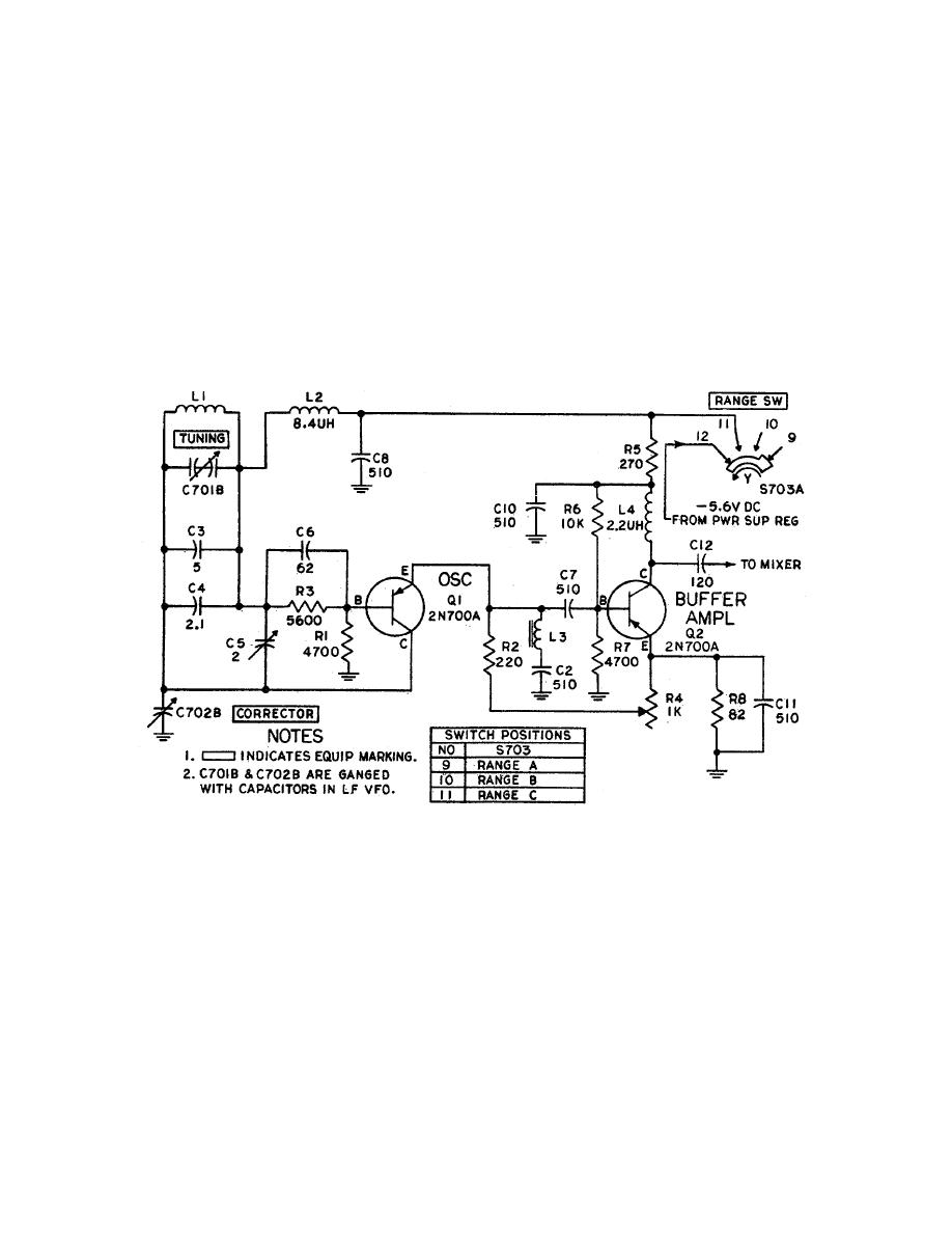
required by the mixer circuit. During the MOD function,
voltage divider which supplies base bias. Diode CR101 is
modulation is applied to Q102 through R109. Capacitor
used to stabilize collector current. Conduction of the
C104, C110, and R106 filter out the medulation before it
diode provides a constant value of forward base bias.
is applied to Q101. The base of Q102 is forward-biased
Capacitor C101 bypasses rf. The oscillator output signal
by the current flowing through voltage divider R109,
is taken from the collector and applied through coupling
R107, and R108. Capacitor C105 and R109 form a
capacitor 102 and S703 to buffer amplifier Q102. When
decoupling circuit. Peaking coil L105, which is the
switch S703 is in the A position, only C102 is used; when
S703 is in the B position, C103 is connected in 'series with
compensation for Q102 (in AN/USM-159 only). R102 is
C102 to reduce the coupling capacitance since less
the collector load for Q102 (in AN/USM159 only). The
coupling is required for this range.
collector output signal is applied through C106 to the
mixer circuit. Resistor R111 prevents emitter current from
exceeding a safe value, and capacitor C107 bypasses rf.
loading and ettenuates the signal to the proper level


 Previous Page
