TM 11-6625-486-14&P
the wires connected to terminals 2, 3, and 4; then, pull
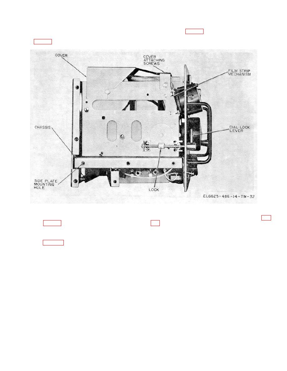
operating level (fig. 6-1). Move the dial mask operating
the dial lamp Fielded cable up through the hole in the
lever away from the filmstrip mechanism by turning the
chassis (fig. 6-1).
RANGE SW to C.
(2)
Disconnect the filmstrip dial mask
(3) With a screwdriver, loosen the DIAL
(6) Under the frequency meter chassis (fig.
LOCK lever (fig. 6-3) and remove the knob.
film container and two under the AUDIO GAIN control)
(4) Remove all of the screws that hold the left
that hold the film mechanism to the chassis. Remove
sideplate. Remove the panel that exposes the filmstrip
these screws while holding the mechanism to prevent it
mechanism (fig. 6-11).
from falling out.
(5) On the meter front panel, rotate the
(7) Carefully slide the film mechanism toward
TUNING control knob counterclockwise until the control
the rear to clear the dial lock shaft; then, slide the unit
reaches its stop position.
out of the left side.


 Previous Page
