TM 11-6625-486-14&P
amplifier will be used. Turn the MIXING FREQUENCY
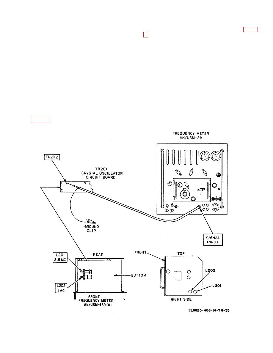
AN/USM-159A or AN/USM-159B, adjust C209A (fig. 6-
MCS switch to 0. Set the counter controls for a
frequency readout of 10 Hz to 10 MHz. Turn on the
e. To adjust the 2.5-MHz frequency, turn the
power and allow the counter to warm up for 15 minutes.
frequency meter RANGES SW to C.
Set the STD GATE TIME SEC switch to 10.
f. On the counter display, read the frequency of
b. On the crystal oscillator circuit board, locate test
the 2.5-megahertz oscillator. The frequency should be
point TP202. Connect the SIGNAL INPUT jack of the
2.5 MHz 12.5 hertz (limits 2.4999875 to 2.5000125
counter to TP202 and the ground clip to the frequency
MHz). If incorrect in the AN/USM159A or AN/USM-
meter chassis.
159B, adjust C209B.
c. Turn the frequency meter FUNCTION SW to
NOTE
CHK and the RANGE SW to A. Allow a 5-minute
If any difficulty is experienced in
warmup period.
obtaining a satisfactory readout on
the counter display, be sure that the
d. On the counter display, read the frequency of
converter GAIN control is not set to
the 1-megahertz crystal oscillator.
The frequency
overdrive the counter and cause an
should be 1 MHz 5 hertz (limits 0.999,995 to
erratic counter readout.
1.000,005 MHz). If incorrect in the AN/USM-159, adjust
L202 (fig.


 Previous Page
