TM 11-6625-486-14&P
The low frequency vfo is a precision oscillator with
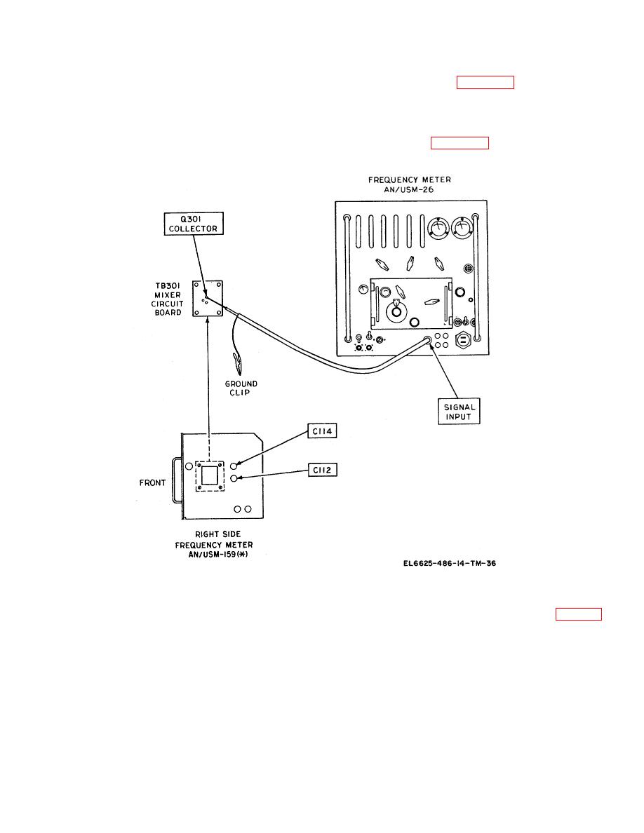
trimmer capacitors. In figure 6-2 trimmer capacitor
tunable frequency ranges of 125 kHz to 250 kHz and
C114 is used to adjust the high end of range A, and
2,500 kHz (2.5 MHz) to 5,000. kHz (5 MHz). The
trimmer capacitor C112 the high end of range B. These
design of the coils, and other frequency determining
trimmers should never be touched unless coilbox Z101
elements in coilbox Z101, sets the low frequency end of
is replaced. It adjustment is necessary, refer to the test
the two vfo frequency ranges and, therefore, no external
equipment setup in figure 6-15 and adjust range, A and
adjustments are provided. The high frequency limit of
B as follows:
the two ranges (250 kHz and 5 MHz) is adjusted with
a. Range A.
(3) On the the mixer circuit board (fig. 6-15),
(1) Set the counter FUNCTION SELECTOR
locate the collector soldered connection of transistor
switch to FREQUENCY and the STD GATE TIME SEC
Q301. Since there is no testpoint at this connection, be
to 1. Turn the counter power on and allow for a 15-
extremely careful not to short the wiring. On the right
minute warmup period. Set the counter for a readout of
side panel of 'he frequency meter, locate trimmer
10 Hz to 10 MHz.
capacitor C114.
(2) Turn the frequency meter FUNCTION SW
(4) Connect the counter SIGNAL INPUT jack
to OPER and the RANGE SW to A.
Turn the
to the collector of Q301 and the ground clip
CORRECTOR knob until the pointer or index is at the
midpoint position. Rotate the TUNING control to center
the 250-kHz checkpoint under the hairline indicator.


 Previous Page
